laser-cut-box
Create a box for a PCB using laser cutting machine
This project is maintained by Hackuarium
It’s in the box
An OpenSCAD project to wrap your PCB in a box
Often we need to create custom boxes to wrap a printed circuit board (PCB) and this may be time consuming.
In this project based on couple of parameters you can quickly and efficiently create DXF files that after laser cutting will provide the different elements to create the box. You may cut any number of holes (round or rectangle) on all the faces of the box and the coordinates will always be relative to the (0,0) that is the bottom left of the PCB.
Coordinates [x,y] of holes corresponds to the center.
You can render the box as a 3D image
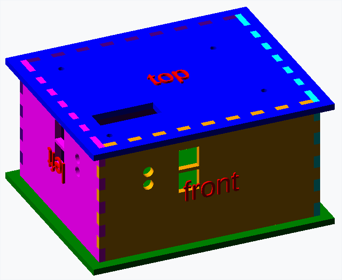
And you can also export easily as a SVG of DXF file for laser cutting.

How to use it
Download OpenSCAD and open the file ‘testBox.scad’.
The comments in the file should be clear enough to use this code.
Exporting as DXF
You should change the following parameters before generating DXF:
- showLabels = false
- 3d = false
You may then render the image and export as DXF.
Code example
$fn=40;

use <pcbbox/pcb.scad>;

pcb(
    length=100,         // length of the PCB
    width=80,           // width of the PCB
    padding=1,          // space around the pcb (between pcb and box)
    thickness=3,        // thickness of the material to create the box
    pcbThickness=1.6,   // thickness of the box
    topToTop=20,        // distance from the top of the PCB to the external top of the box
    bottomToBottom=40,  // distance from the bottom of the PCB to the external bottom of the box
    extend=[10,10,0,0,0,0],          // should top and bottom 'extend' in order to assemble the box without glue
    screws=[            // position of holes to fix the PCB
        [5,5],
        [10,70],
        [85,15],
        [80,60]
    ],
    screwDiameter=3,    // diameter of the screws to fix the PCB
    topHoles=[          // holes to put on the top of the box
        [20,20,30,10]   // 0,0 is the bottom left of the PCB
    ],
    bottomHoles=[       // holes to put on the bottom of the box
        [40,40,10],     // array witlh 3 parameters = a circle [x,y,diameter]
        [20,20,5,5]     // array with 4 parameters = a rectangle [x,y,width,depth]
    ],
    frontHoles=[        // holes in front of the box, over the PCB
        [20, 2.5, 5],
        [40,5,10,10]
    ],
    frontHolesB=[       // holes in front of the box, under the PCB
        [20,2.5,5],
        [40,5,10,10]
    ],
    backHoles=[         // holes in the back of the box, over the PCB
        [20,2.5,5],
        [40,5,10,10]
    ],
    backHolesB=[        // holes in front of the box, under the PCB
        [20,2.5,5],
        [40,5,10,10]
    ],
    leftHoles=[         // holes on the left of the box, over the PCB
        [20,2.5,5],
        [40,5,10,10]
    ],
    leftHolesB=[        // holes on the left of the box, under the PCB
        [20,2.5,5],
        [40,5,10,10]
    ],
    rightHoles=[        // holes on the right of the box, over the PCB
        [20,2.5,5],
        [40,5,10,10]
    ],
    rightHolesB=[       // holes on the right of the box, under the PCB
        [20,2.5,5],
        [40,5,10,10]
    ],
    showLabels=true,    //should we show the labels
    labelsSize=10,      // size of the labels
    3d=true             // 3d rendering or just 2d ?
);
Screwing the PCB
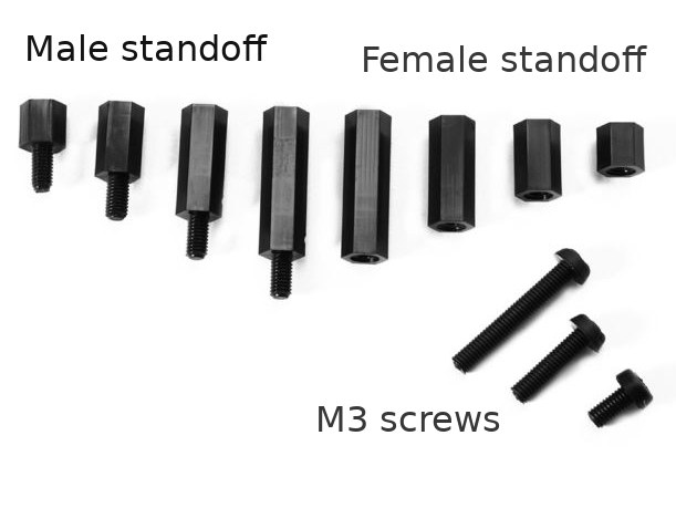
We recently often use black nylon M3 screw, standoff and spacer.
In order to fix the PCB we have the following sequence:
- M3 screw
- top of the case
- column standoff female spacer
- PCB
- column standoff male spacer
- bottom of the case
- M3 screw (we take 40 mm screws that we cut if needed)